| Select Rooms
|
Click to select and deselect the rooms displayed in
the report. Clicking the icon changes the layout of the dialog. Rooms can be
selected/deselected individually by clicking on them, or select/deselect all by
clicking the two buttons provided.
-
Select all — Used to select all rooms
with a single click.
-
Deselect all — Used to deselect all
rooms with a single click.
-
OK — Applies all changes and closes the
Room selection view.
-
Cancel — Cancels all changes, and closes
the Room selection view.
|
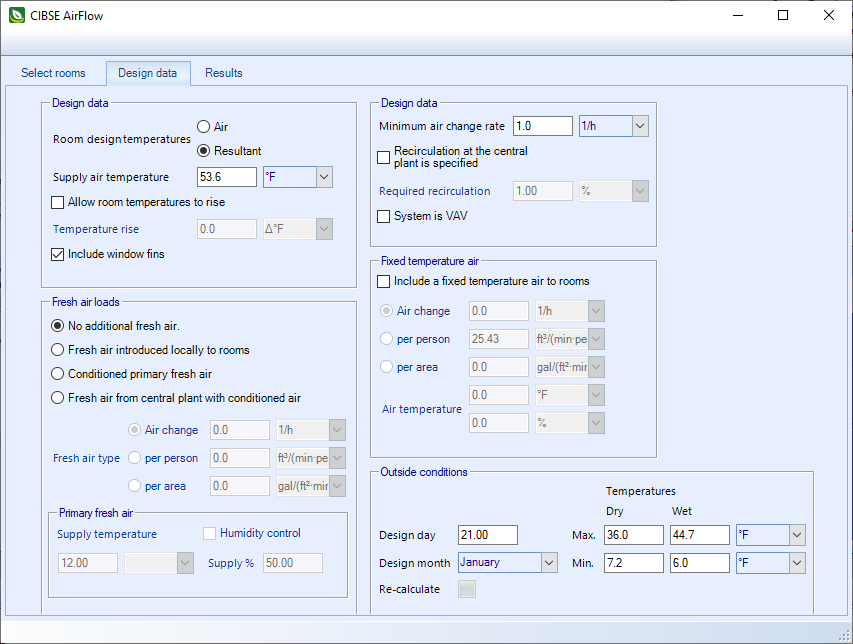
| Design Data
|
A set of default data must be set up to define the heat gain and
air flow basis for rooms. All rooms are subjected to the default data, unless
you define some data variations and set some rooms up as different from the
default.
-
Room design temperatures — Room design
temperatures may be design
Air or design
Resultant temperatures. This affects the
heat gain calculations for rooms.
- Supply
air temperature - The value entered here is used to compute the
required air flow rate to the room from a heat flow viewpoint.
- Temperature
rise - An allowable temperature rise for rooms may be defined.
Reduces heat gains if specified.
- Include
external shading - When on, the calculation checks if each window
is shaded by external obstructions at each hour of the day.
- Include
window fins - When on, shaded windows receive diffuse solar
radiation only.
- Minimum
air change rate - This must be defined for rooms, and may,
depending on the value specified, increase the calculated air flow to rooms.
- Recirculation at the
central plant is specified - Specified as a recirculation
percentage. When on, the computed fresh air requirement is computed from the
recirculation percentage, rather than from the specified fresh air data.
- System is VAV - When
on, the system is defined as VAV (variable air volume). When off, a constant
volume system is assumed.
| Setting | Description |
|---|
| Fresh air loads
|
A fresh air load can optionally be included in the load
calculation. Contains controls to define one.
- No
additional fresh air - When on, no additional fresh air is included
in the calculation.
-
Fresh air introduced locally to rooms - Affects the room load when
on.
- Conditioned primary
air - When on, conditioned air is supplied at the defined supply
temperature, with an optional supply humidity control. Conditioned primary air
affects both room loads and central plant loads.
Note: If
Conditioned primary air is
specified, and this fresh air requires heating at the central plant, when the
building requires cooling (or vice versa), then the fresh air heat load is
excluded from the central plant loads.
-
Fresh air from the central plant with conditioned air - When on,
forms part of the supply air and becomes a load on the central plant.
- Fresh air type
- Fresh air is supplied to all included rooms using one of the following
criteria:
- Air change rate
- Fresh air requirement
per person
- Fresh air requirement per
square meter
|
| Fixed temperature air
|
A fixed temperature air supply to rooms can be specified.
This could be a fixed air flow from another space, or a tempered air supply to
rooms.
Each room included in the calculation is subject to the
specified fixed temperature air supply, which is assumed to occur throughout
the day and night.
- Include a fixed temperature
air supply to rooms - When on, you can select from one of the
following criteria.
- Air change rate
- Fresh air requirement
per person
- Fresh air requirement per
square meter
- Air
temperature and
% saturation of the fixed air
supply must also be specified.
|
| Outside conditions
|
|
|
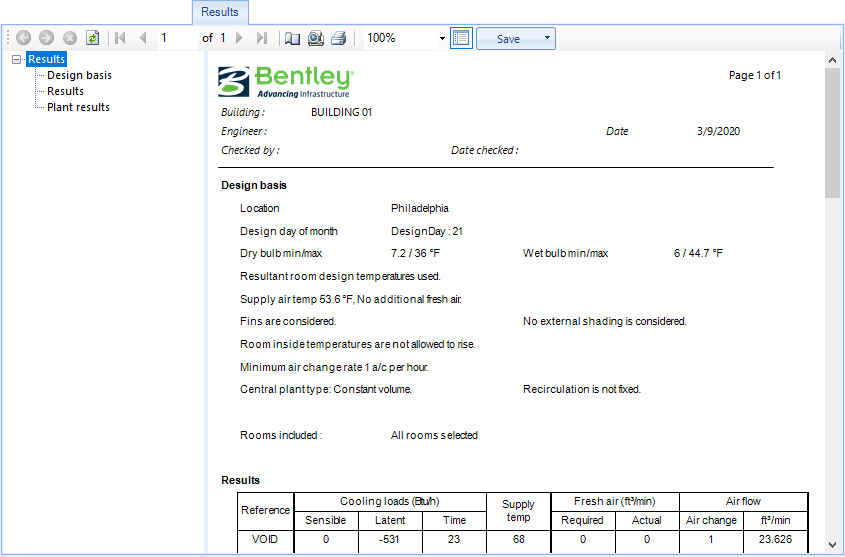
| Results
|
Contains controls used to view reports detailing the CIBSE Air
Flow calculation results.
| Setting | Description |
|---|
| Toolbar
|
Located along the top of each of the dialog tabs,
the toolbar provides controls for viewing, navigating, printing and exporting
reports.
The controls from left to right are:
- Navigate
back/forward in history - Disabled
- Stop - Click to stop
regeneration of the reports.
- Refresh - Click to
refresh the results being displayed.
- First page - Click
to jump to the first page of the report. Enabled when
"Switch to print preview" is selected.
- Previous page -
Click to jump to the previous page in the report. Enabled when
"Switch to print preview" is selected.
- Next page - Click to
jump to the next page in the report. Enabled when
"Switch to print preview" is selected.
- Last page - Click to
jump to the last page of the report. Enabled when
"Switch to print preview" is selected.
- Page setup - Opens
the Page Setup dialog.
- Switch to print
preview / interactive view - Click to change the layout of the report. The
print preview allows you to view each printed page. It activates the navigation
buttons (first, previous, next, last page). The interactive view (default)
displays the reports in a single scrollable page.
- Print report -
Prints the report.
- Zoom - Selects a
zoom factor from the available drop down menu.
- Close document map -
Click to hide/unhide the table of contents (left panel).
- Save - Used to save
as/export the report to the following formats:
- Acrobat (PDF)
file
- CSV (comma
delimited)
- Excel 97-2003
- Rich Text Format
- TIFF file
- Web Archive
|
| Design basis
|
Used to display key design parameters considered for the
calculation. Selecting Design basis in the selector panel (left) updates the
reports display panel (right), scrolling to the Design basis display.
|
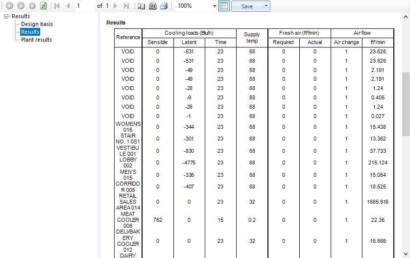
| Results
|
Displays results for each room: Sensible and latent gains
are shown, together with the computed supply air temperature for each room. The
total air flow (m3/s) and air change rate is given. If a constant
volume system has been specified, then the actual fresh air flow to each room
is shown.
|
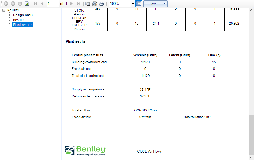
| Plant results
|
For the central plant, the peak coincident building load
is shown (hour by hour simultaneous peak for all rooms), together with the peak
time. The fresh air is also shown and the total plant load includes the
building load and the fresh air load. The time of the peak may differ from the
building peak, as the fresh air load may move the total peak. The fresh air
load is computed using the actual fresh air load at the central plant and takes
into account the mean return air temperature for the system.
|
|
 Used to calculate the total air
flow to all rooms included, assuming either a constant volume or VAV system.
Used to calculate the total air
flow to all rooms included, assuming either a constant volume or VAV system.